The ESP32-CAM is a powerful, low-cost module that combines an ESP32-S microcontroller with an OV2640 camera, enabling you to create a video streaming web server accessible from any browser on your local network. While an older example in the Arduino library once offered built-in face recognition, the current standard method focuses on reliable, real-time video streaming as a foundation for your own projects. This comprehensive 2026 guide, built on years of hands-on testing with ESP32 hardware, will walk you through every step—from wiring and uploading code to accessing your live stream and troubleshooting common issues.
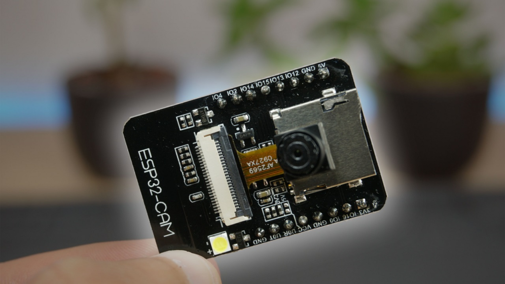
Introduction to the ESP32-CAM: Capabilities and Hardware
The ESP32-CAM, notably the popular AI-Thinker variant, packs significant features into a tiny, sub-$10 module:
-
Core Processor: A low-power 32-bit ESP32-S chip, clockable up to 160MHz.
-
Connectivity: Built-in 802.11 b/g/n Wi-Fi and Bluetooth for wireless communication.
-
Memory: 520KB internal SRAM and 4MB external PSRAM (crucial for image processing).
-
Camera: Integrated OV2640 sensor capable of JPEG output at various resolutions.
-
Storage: A microSD card slot for saving photos or video clips.
-
GPIOs: Multiple pins for UART, SPI, I2C, PWM, and ADC, allowing connection to sensors and actuators.
Critical Hardware Setup and Pinout
A key challenge is that the ESP32-CAM lacks a built-in USB port. You must use an external programmer, such as an FTDI module or a dedicated ESP32-CAM-MB USB adapter.
Power Warning: The ESP32-CAM can be power-hungry, especially when the flash LED is active. Always use a stable 5V power source connected to the 5V pin. Using 3.3V or an underpowered USB port is a leading cause of instability and boot failures.
For programming, these are the essential connections to an FTDI programmer:
⚠️ Important: After uploading your code, you must disconnect GPIO 0 from GND for the board to boot normally. A simple way to manage this is to use a jumper wire that you can remove after programming.
Step-by-Step Project Setup
Step 1: Install the ESP32 Board in Arduino IDE
Before writing code, you must add ESP32 support to the Arduino IDE.
-
Open Arduino IDE (v2.x or later is recommended).
-
Go to File > Preferences. In the “Additional Boards Manager URLs” field, enter: https://espressif.github.io/arduino-esp32/package_esp32_index.json
-
Navigate to Tools > Board > Boards Manager..., search for “esp32“, and install the “ESP32 by Espressif Systems” package.
Step 2: Prepare and Configure the Example Code
The Arduino-ESP32 core includes an excellent example for camera streaming.
-
Go to File > Examples > ESP32 > Camera and open the CameraWebServer example.
-
Configure Your Network: Find these lines and insert your Wi-Fi credentials:
const char* ssid = "YOUR_NETWORK_NAME";
const char* password = "YOUR_NETWORK_PASSWORD";
-
Select Your Camera Model: Find the camera model definitions. For the common AI-Thinker module, comment out other models and ensure this line is active:
#define CAMERA_MODEL_AI_THINKER
Step 3: Upload the Code to the ESP32-CAM
This is the most critical and often problematic step. Follow meticulously:
-
Connect Wires: Assemble the circuit as shown in the table above, ensuring GPIO 0 is connected to GND.
-
Select Board and Port: In the Arduino IDE:
-
Upload: Click the upload button. As the code compiles and uploads, you may see “Connecting…” in the status bar. If it hangs, press the physical RST (Reset) button on the ESP32-CAM board. This often triggers the upload to proceed.
-
Finalize: After a successful “Done uploading” message:
-
Disconnect the GPIO 0 wire from GND.
-
Open the Serial Monitor (Tools > Serial Monitor).
-
Set the baud rate to 115200.
-
Press the RST button again. The board will boot, connect to Wi-Fi, and print its IP address (e.g., 192.168.1.105) to the Serial Monitor. Copy this address.
Accessing Your Video Streaming Web Server
On any device connected to the same local Wi-Fi network (phone, laptop, tablet):
-
Open a web browser (Chrome, Firefox, Safari).
-
In the address bar, type the IP address you copied from the Serial Monitor.
-
You should see the ESP32-CAM web interface. Click “Start Streaming” to begin the live video feed.
Interface Features:
-
Start Streaming / Stop Streaming: Controls the live MJPG video feed.
-
Get Still: Captures and displays a single high-resolution JPEG photo.
-
Resolution Dropdown: Change the video stream resolution (e.g., UXGA, SVGA, VGA). Lower resolutions like VGA (640×480) provide a smoother frame rate.
-
Quality and Brightness Sliders: Adjust various image parameters in real-time.
-
Face Detection: The current version of the library typically includes a basic “Face Detection” toggle. This draws boxes around detected faces but does not include “Face Recognition” (identifying specific individuals) by default. Adding recognition requires significant additional coding and training, which is beyond the scope of this foundational example.
In-Depth Code Explanation and Customization
Understanding the key parts of the CameraWebServer example empowers you to modify it.
1. Camera Initialization
The setup() function initializes the camera with a predefined configuration (config).
camera_config_t config;
config.ledc_channel = LEDC_CHANNEL_0;
config.ledc_timer = LEDC_TIMER_0;
config.pin_d0 = 5;
config.pin_d1 = 18;
config.frame_size = FRAMESIZE_SVGA;
config.jpeg_quality = 12;
config.fb_count = 2;
esp_err_t err = esp_camera_init(&config);
if (err != ESP_OK) {
Serial.printf("Camera init failed with error 0x%x", err);
return;
}
2. The Streaming Server
The example creates an asynchronous web server that handles multiple connections efficiently. When you access the root (/) URL, it serves the HTML/JavaScript page that contains the video viewer and controls. The /stream endpoint delivers the continuous Motion-JPEG (MJPEG) video feed, which is simply a stream of JPEG images.
Simple Modification: Saving a Photo to microSD Card
You can extend the example to save “Get Still” photos. First, ensure the SD card is formatted as FAT32 and inserted. Add this function and modify the server handler for the still capture:
#include "SD_MMC.h"
void setup() {
if(!SD_MMC.begin()){
Serial.println("SD Card Mount Failed");
return;
}
}
{
camera_fb_t * fb = esp_camera_fb_get();
if(!fb) { }
String path = "/photo_" + String(millis()) + ".jpg";
File file = SD_MMC.open(path.c_str(), FILE_WRITE);
if(file){
file.write(fb->buf, fb->len);
file.close();
Serial.println("Photo saved: " + path);
}
esp_camera_fb_return(fb);
}
Troubleshooting: Fixing Common ESP32-CAM Issues
Here are solutions to the most frequent problems, based on extensive community experience:
Beyond Basic Streaming: Project Ideas
Your working video server is a launchpad for advanced IoT projects:
-
Home Security Monitor: Combine with a PIR motion sensor to capture and save photos to the SD card upon movement detection, then email them via IFTTT.
-
Baby/Pet Monitor: Integrate audio streaming and embed the video feed into a custom dashboard like Node-RED.
-
Time-Lapse Photography: Modify the code to take a picture every minute and save it to the SD card.
-
Video Doorbell: Add a doorbell button that triggers a photo capture and sends a notification to your phone.
This guide provides the foundational expertise to deploy a robust ESP32-CAM video streaming server. By methodically following the hardware, code, and troubleshooting steps, you transform an inexpensive module into a versatile eye for your Internet of Things projects. The journey from a bare board to a live video feed encapsulates the power and accessibility of modern embedded systems.