Unlocking Real-Time Responsiveness with ESP32 Interrupts
In the world of ESP32 embedded systems programming, achieving efficient and responsive applications often hinges on one critical concept: GPIO interrupts. Unlike continuous polling, which wastes precious processor cycles, interrupts allow the ESP32 to react instantaneously to external events—like a button press, a sensor threshold breach, or a motion detection—by temporarily pausing its main task. This comprehensive guide, updated for modern development practices, will transform you from an interrupt novice to a confident practitioner. We’ll dive deep into the attachInterrupt() function, explore robust debouncing techniques, build practical projects, and uncover advanced best practices often overlooked in beginner tutorials, ensuring your ESP32 projects are both responsive and reliable.
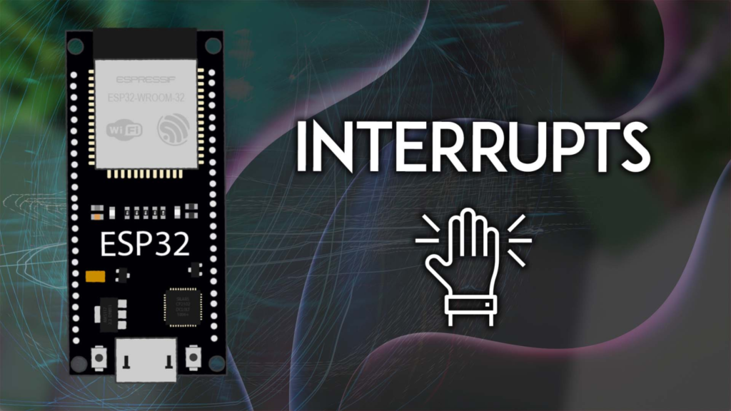
Understanding the Core: What Are Interrupts and Why They Matter
An interrupt is a hardware-driven signal that demands the processor’s immediate attention. Imagine a doorbell: you don’t stand by the door continuously checking if someone is there (polling); instead, you go about your business until the ring (interrupt) calls you to act. In microcontroller terms:
-
Main Program Execution: Your loop() function runs normally.
-
Event Occurs: A GPIO pin changes state based on your defined mode (e.g., a button is pressed, pulling the pin from HIGH to LOW).
-
Context Switch: The processor immediately saves its state and jumps to a special function called an Interrupt Service Routine (ISR).
-
ISR Execution: A short, dedicated piece of code runs to handle the event.
-
Resume: The processor reloads its saved state and seamlessly continues the main program from where it left off.
This mechanism is indispensable for:
-
Battery-powered projects, where minimizing CPU active time is key.
-
Real-time control systems, where millisecond delays are unacceptable.
-
Multi-tasking applications, where the ESP32 must manage several asynchronous inputs.
ESP32 Interrupt Capabilities: Beyond the Basics
The ESP32 is exceptionally well-equipped for interrupts. Virtually every GPIO pin that can be configured as an input can also serve as an interrupt pin. This flexibility is far greater than on classic Arduino boards. Furthermore, the ESP32 supports multiple types of interrupts:
-
External GPIO Interrupts (the focus of this guide): Triggered by external voltage changes on a pin.
-
Timer Interrupts: Triggered by internal timers for periodic tasks.
-
Touch Interrupts: Unique to the ESP32, triggered by capacitive touch sensing.
Prerequisites: Gearing Up for Development
To follow this guide, ensure your development environment is ready:
-
Arduino IDE or VS Code with PlatformIO: We recommend PlatformIO for better project management and library handling, though the code is fully compatible with the Arduino IDE.
-
ESP32 Board Package: Installed via the Arduino Boards Manager or PlatformIO.
-
Hardware:
-
An ESP32 development board (like the ESP32 DevKit).
-
A pushbutton and/or a PIR motion sensor (HC-SR501).
-
An LED and a 220Ω resistor (for the PIR example).
-
Breadboard and jumper wires.
A Deep Dive into attachInterrupt(): Syntax and Parameters
The gateway to using interrupts in the Arduino framework is the attachInterrupt() function. Understanding its arguments is crucial.
attachInterrupt(digitalPinToInterrupt(pin), ISR_function, mode);
Let’s break down each parameter with expert-level insight:
1. GPIO Pin (digitalPinToInterrupt(pin))
While you can use the raw GPIO number, digitalPinToInterrupt() is the recommended, portable practice. It maps the physical pin to the internal interrupt number. On the ESP32, all input-capable pins (like GPIOs 0, 2, 4, 5, 12-19, 21-23, 25-27, 32-33) work.
2. The ISR Callback Function (ISR_function)
This is the function executed when the interrupt triggers. Writing proper ISRs is where many developers stumble. Adhere to these non-negotiable rules:
-
Keep it Short and Fast: The ISR should execute in microseconds. Lengthy operations block all other interrupts and tasks, leading to missed events or system instability.
-
No delay() or Blocking Calls: Never use delay(), lengthy loops, or Serial prints (Serial.print()) inside an ISR. These functions rely on interrupts themselves and will fail or crash the system.
-
Use the ARDUINO_ISR_ATTR Macro: This attribute ensures your ISR is placed in the ESP32‘s fast Internal RAM (IRAM) instead of slower Flash memory. Missing this can cause crashes if the Flash is busy during an interrupt.
-
Declare Shared Variables as volatile: This instructs the compiler not to optimize this variable and to always read it from memory. This is critical because the variable can be changed in the ISR (asynchronous to the main code).
Example of a Properly Declared ISR:
void ARDUINO_ISR_ATTR handleInterrupt() {
interruptFlag = true;
interruptCounter++;
}
3. The Interrupt Mode (mode)
This defines which electrical change on the pin triggers the interrupt. Choosing the right mode is critical for your application’s logic.
Expert Advice: Prefer RISING/FALLING over CHANGE where possible, as CHANGE can double-trigger for a single event. Avoid HIGH/LOW modes unless you have a specific, controlled use case and implement a manual debouncing/deactivation logic, as they can lock the processor in a continuous interrupt loop.
Project 1: Professional-Grade Button Press Detection with Debouncing
Let’s apply this knowledge. A simple button press is plagued by contact bounce—a rapid, physical oscillation that creates multiple electrical transitions in milliseconds. Without handling it, a single press registers as dozens.
Circuit Connection
Connect a pushbutton between GPIO 18 and GND. We utilize the ESP32‘s internal pull-up resistor, so no external resistor is needed.
The Code: Robust and Debounced
#include <Arduino.h>
const uint8_t BUTTON_PIN = 18;
volatile bool buttonPressedFlag = false;
volatile unsigned long lastDebounceTime = 0;
void ARDUINO_ISR_ATTR isrButton() {
unsigned long currentMicros = micros();
if ((currentMicros - lastDebounceTime) > 200000) {
buttonPressedFlag = true;
lastDebounceTime = currentMicros;
}
}
void setup() {
Serial.begin(115200);
pinMode(BUTTON_PIN, INPUT_PULLUP);
attachInterrupt(digitalPinToInterrupt(BUTTON_PIN), isrButton, FALLING);
Serial.println("Interrupt-driven button system ready.");
}
void loop() {
if (buttonPressedFlag) {
Serial.println("Button press detected and handled!");
buttonPressedFlag = false;
}
}
Why This Code is Superior:
-
Efficient Debouncing: Uses a time threshold (200000µs) to ignore spurious triggers within the bounce period. The value can be adjusted based on your button’s physical characteristics (typically 50-200ms).
-
Correct Trigger Mode: Uses FALLING because the pin is pulled up to HIGH and goes LOW when pressed.
-
Flag-Based Design: The ISR only sets a volatile flag. All “heavy lifting” (like Serial.print) is done in the loop(). This is the golden rule of interrupt handling.
Project 2: Motion-Activated System with PIR Sensor
PIR (Passive Infrared) sensors output a HIGH signal when motion is detected. This is a perfect, real-world use case for interrupts in security or automation systems.
Circuit Connection
-
Connect the PIR sensor’s VCC to 5V (or 3.3V, check your sensor), GND to GND.
-
Connect the sensor’s OUT pin to GPIO 19.
-
Connect an LED (with a 220Ω series resistor) to GPIO 21.
The Code: Motion-Activated LED
#include <Arduino.h>
const uint8_t PIR_PIN = 19;
const uint8_t LED_PIN = 21;
volatile bool motionDetected = false;
unsigned long motionStartTime = 0;
const unsigned long LIGHT_DURATION = 5000;
void ARDUINO_ISR_ATTR isrPIR() {
motionDetected = true;
motionStartTime = millis();
}
void setup() {
Serial.begin(115200);
pinMode(PIR_PIN, INPUT);
pinMode(LED_PIN, OUTPUT);
digitalWrite(LED_PIN, LOW);
attachInterrupt(digitalPinToInterrupt(PIR_PIN), isrPIR, RISING);
Serial.println("Motion detection system armed.");
}
void loop() {
if (motionDetected) {
Serial.println("ALERT: Motion detected!");
digitalWrite(LED_PIN, HIGH);
motionDetected = false;
}
if (digitalRead(LED_PIN) == HIGH && (millis() - motionStartTime) > LIGHT_DURATION) {
digitalWrite(LED_PIN, LOW);
Serial.println("Light turned off.");
}
}
Advanced Techniques and Pro Tips
-
Disabling Interrupts (detachInterrupt): Use detachInterrupt(digitalPinToInterrupt(PIN)); when you no longer need to monitor an event. This is useful for power saving or changing interrupt modes dynamically.
-
Critical Sections with portENTER_CRITICAL: If a block of code in your main loop must not be interrupted, wrap it with critical sections. Use sparingly!
portENTER_CRITICAL(&timerMux);
criticalVariable++;
portEXIT_CRITICAL(&timerMux);
-
Interrupt Priorities (For FreeRTOS): When using the ESP32‘s FreeRTOS capabilities, you can assign priorities to different interrupt sources. Higher-priority interrupts can preempt lower-priority ones. This requires working directly with the ESP32‘s hardware interrupt matrix and is an advanced topic.
-
ISR-Friendly Data Structures: For passing data from ISR to main loop, consider using lock-free queues (like FreeRTOS queues) if you’re using an RTOS, or simple ring buffers for byte streams.
Troubleshooting Common Interrupt Pitfalls
Conclusion: Integrating Interrupts into Your Projects
Mastering ESP32 GPIO interrupts fundamentally changes how you design responsive systems. By moving from passive polling to active event-driven programming, you free up the processor, reduce power consumption, and guarantee timely reactions to critical events.
Start by integrating a simple debounced button into your next project. Then, experiment with connecting multiple sensors (e.g., a button on GPIO 18 and a PIR on GPIO 19) to see how the ESP32 effortlessly manages concurrent, asynchronous events. Remember the core tenets: keep ISRs ultra-lean, use volatile flags, and handle logic in the main loop.
For further exploration, delve into the ESP32‘s timer interrupts for precision timing or touch sensor interrupts for creating capacitive controls. The world of interrupt-driven design is vast, and your newfound skills are the key to unlocking the full potential of the powerful ESP32 microcontroller.
Contact Us