Why Digital GPIOs Are Fundamental to ESP32 Projects
Every ESP32 project—from simple LED blinkers to complex home automation systems—relies on digital inputs and outputs. Digital pins detect binary states (pressed/released, on/off) and control digital devices. With approximately 34 usable GPIO pins (with limitations), the ESP32 offers tremendous flexibility for connecting sensors, actuators, displays, and communication modules.
Key Advantages of ESP32 Digital GPIOs:
-
Flexible pin assignment: Most pins can be configured as either inputs or outputs
-
Built-in pull-up/pull-down resistors: Eliminate the need for external resistors in many cases
-
High drive capability: Can source/sink sufficient current for LEDs and relays
-
Interrupt capability: Respond instantly to input changes without constant monitoring
Hardware Overview: Understanding ESP32 Pin Limitations
Before connecting any components, it’s crucial to know which pins are truly available. Not all ESP32 pins behave equally:
Restricted Pins to Avoid
-
GPIOs 6-11: Internally connected to the ESP32‘s SPI flash memory. Using these can crash your program.
-
GPIOs 34-39: Input-only pins. Cannot be used as outputs or with internal pull-up/pull-down resistors.
-
Strapping pins (GPIOs 0, 2, 4, 5, 12, 15): Affect boot behavior—use cautiously during development.
Versatile Digital Pins
Most other GPIOs (0-5, 12-19, 21-23, 25-27, 32-33) work as both digital inputs and outputs. For beginners, GPIOs 4, 5, 18, and 19 are excellent starting points as they lack special restrictions.
Core Functions for Digital I/O Programming
The Arduino IDE provides three essential functions for digital GPIO control:
1. pinMode(pin, mode) – Pin Configuration
Sets a GPIO as either INPUT or OUTPUT. Always configure pins in your setup() function before using them.
Common mistake: Forgetting to set pin mode, which leads to unpredictable behavior.
2. digitalWrite(pin, value) – Controlling Outputs
Sets an output pin to either HIGH (3.3V) or LOW (0V).
digitalWrite(5, HIGH);
digitalWrite(5, LOW);
3. digitalRead(pin) – Reading Inputs
Returns HIGH or LOW based on the voltage detected at an input pin.
int buttonState = digitalRead(4);
Practical Example: LED Control with Push Button
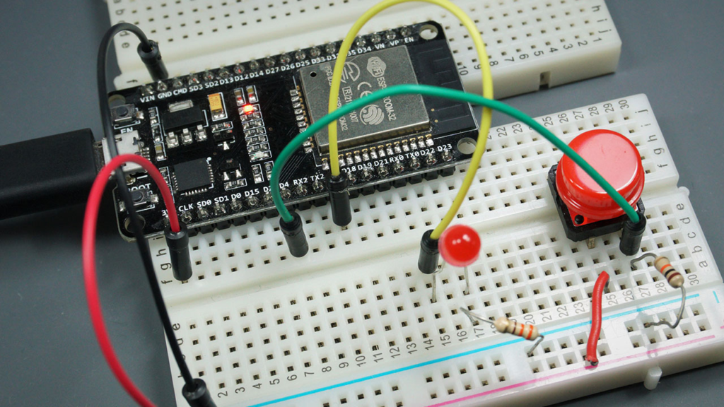
Let’s build on the basic “button controls LED” circuit with enhanced functionality and debugging.
Enhanced Circuit Diagram
-
LED: Connect anode (long leg) to GPIO 5 through a 220Ω resistor, cathode to GND
-
Push button: Connect one terminal to GPIO 4, other terminal to 3.3V
-
Crucial addition: Add a 10kΩ pull-down resistor between GPIO 4 and GND
Professional-Grade Code with Debugging
const int BUTTON_PIN = 4;
const int LED_PIN = 5;
int lastButtonState = LOW;
int buttonPressCount = 0;
unsigned long lastDebounceTime = 0;
unsigned long debounceDelay = 50;
void setup() {
Serial.begin(115200);
Serial.println("ESP32 Digital I/O Example Initialized");
pinMode(BUTTON_PIN, INPUT);
pinMode(LED_PIN, OUTPUT);
digitalWrite(LED_PIN, LOW);
Serial.print("Monitoring button on GPIO ");
Serial.println(BUTTON_PIN);
}
void loop() {
int currentButtonState = digitalRead(BUTTON_PIN);
if (currentButtonState != lastButtonState) {
lastDebounceTime = millis();
}
if ((millis() - lastDebounceTime) > debounceDelay) {
if (currentButtonState == HIGH && lastButtonState == LOW) {
buttonPressCount++;
Serial.print("Button pressed! Total presses: ");
Serial.println(buttonPressCount);
digitalWrite(LED_PIN, !digitalRead(LED_PIN));
if (digitalRead(LED_PIN) == HIGH) {
Serial.println("LED turned ON");
} else {
Serial.println("LED turned OFF");
}
}
}
lastButtonState = currentButtonState;
delay(10);
}
Code Explanation: Beyond the Basics
-
Debouncing: Mechanical buttons physically “bounce” when pressed, creating multiple rapid state changes. Our debouncing logic waits 50ms after a change before registering it.
-
Serial debugging: Provides real-time feedback in the Serial Monitor—invaluable for troubleshooting.
-
Toggle logic: Each button press alternates the LED state rather than requiring constant pressure.
-
Efficient polling: Uses millis() for timing instead of blocking delay() calls.
Advanced Input Techniques
Using Internal Pull-up Resistors
For simpler wiring, use the ESP32‘s built-in pull-up resistors:
pinMode(BUTTON_PIN, INPUT_PULLUP);
With INPUT_PULLUP, connect your button between the GPIO pin and GND (not 3.3V).
Pin State Change Interrupts
For immediate response without constant polling:
attachInterrupt(digitalPinToInterrupt(BUTTON_PIN), buttonPressed, CHANGE);
void buttonPressed() {
}
Warning: Keep ISR code extremely short—avoid Serial.print() or complex operations.
Real-World Application: Smart Button with Multiple Functions
Transform the basic example into a practical smart home component:
void loop() {
int buttonState = digitalRead(BUTTON_PIN);
if (buttonState == HIGH) {
unsigned long pressStart = millis();
while (digitalRead(BUTTON_PIN) == HIGH) {
delay(10);
}
unsigned long pressDuration = millis() - pressStart;
if (pressDuration < 50) {
}
else if (pressDuration < 500) {
Serial.println("Short press - toggle light");
}
else if (pressDuration < 3000) {
Serial.println("Medium press - dim light");
}
else {
Serial.println("Long press - factory reset");
}
}
}
Troubleshooting Common Issues
1. Unstable/Noisy Input Readings
Symptoms: Random HIGH/LOW fluctuations without button press
Solutions:
-
Always use pull-up or pull-down resistors (internal or external)
-
Add a 0.1µF capacitor between input pin and GND
-
Implement software debouncing as shown above
2. ESP32 Won’t Upload Code
Symptoms: “Failed to connect” errors during upload
Solutions:
-
Hold the BOOT button when upload begins
-
Check Tools > Board selection matches your ESP32 model
-
Try different USB cables (some charge-only cables don’t transmit data)
3. LED Doesn’t Light/Is Very Dim
Solutions:
-
Verify LED orientation (long leg to positive)
-
Ensure resistor value is appropriate (220-470Ω)
-
Check you’re writing HIGH to the correct pin
4. WiFi Interference with GPIOs
Critical note: When WiFi is active, avoid using GPIOs 6-11, 16, 17. For ADC2 pins (GPIOs 0, 2, 4, 12-15, 25-27), you may experience conflicts when using WiFi simultaneously.
Expanding Your Project: Next Steps
Once you’ve mastered basic digital I/O, explore these related concepts:
-
Analog Inputs: Read variable voltages with analogRead() for sensors like potentiometers
-
PWM Output: Simulate analog output with analogWrite() for LED fading, motor control
-
Touch Sensing: Use ESP32‘s built-in capacitive touch sensors on designated pins
-
Multiple Devices: Learn I2C and SPI communication to connect many sensors to few pins
Essential Best Practices
-
Always initialize pins in setup() before using them in loop()
-
Include current-limiting resistors for LEDs (220Ω-1kΩ)
-
Use descriptive variable names (ledPin not pin13)
-
Implement debouncing for all mechanical switches
-
Test each component separately before combining complex circuits
-
Document your pin assignments with comments or diagrams
From Learning to Application
This digital I/O foundation enables countless ESP32 projects:
-
Home automation: Light controls, security sensors, smart switches
-
IoT devices: Button-controlled webhooks, status indicators
-
Robotics: Limit switches, motor controllers, sensor arrays
-
Prototyping: User interfaces, debug indicators, mode selectors
Remember: Every complex ESP32 project builds upon these basic digital input/output concepts. Start simple, master the fundamentals, and gradually add complexity.
Need Help? If your circuit isn’t working:
-
Double-check all connections against the schematic
-
Verify your GPIO numbers match the physical pins
-
Check the Serial Monitor for debugging messages
-
Ensure power is connected (USB or external 5V)
Share Your Project! Modified the code for your own use? Created an interesting application? Share your experiences in the comments to help other makers learn from your journey.
Ready to advance? Explore our ESP32 GPIO Reference Guide for complete pin details and special functions, or check out our ESP32 PWM tutorial for motor and LED dimming control.